
ACCESSORIES · PROTECTION & CONCLUSION
Protection &
Connecting boxes.
Enquire connection boxes and protective components for your PV system.
From the generator connection to the AC distributor: Ask your needs at TP ENERGY. We will coordinate the required components with you based on your system and protection concept.
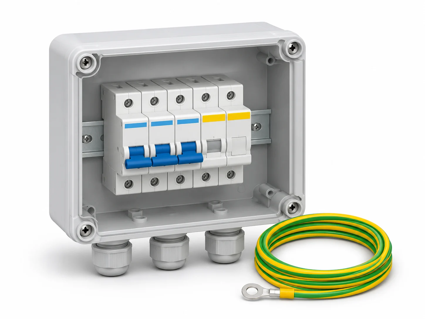
The protection task determines the execution.
Select the required accessory type. A click on the icon image opens the properties. About "Inquire your offer" let us know your needs – equipment and design will be clarified on the basis of your documents.
On the DC side.
Connection boxes, conductors and switches take on different tasks between PV modules and inverters. A housing can accommodate several of these functions; the equipment is derived from the plant design.
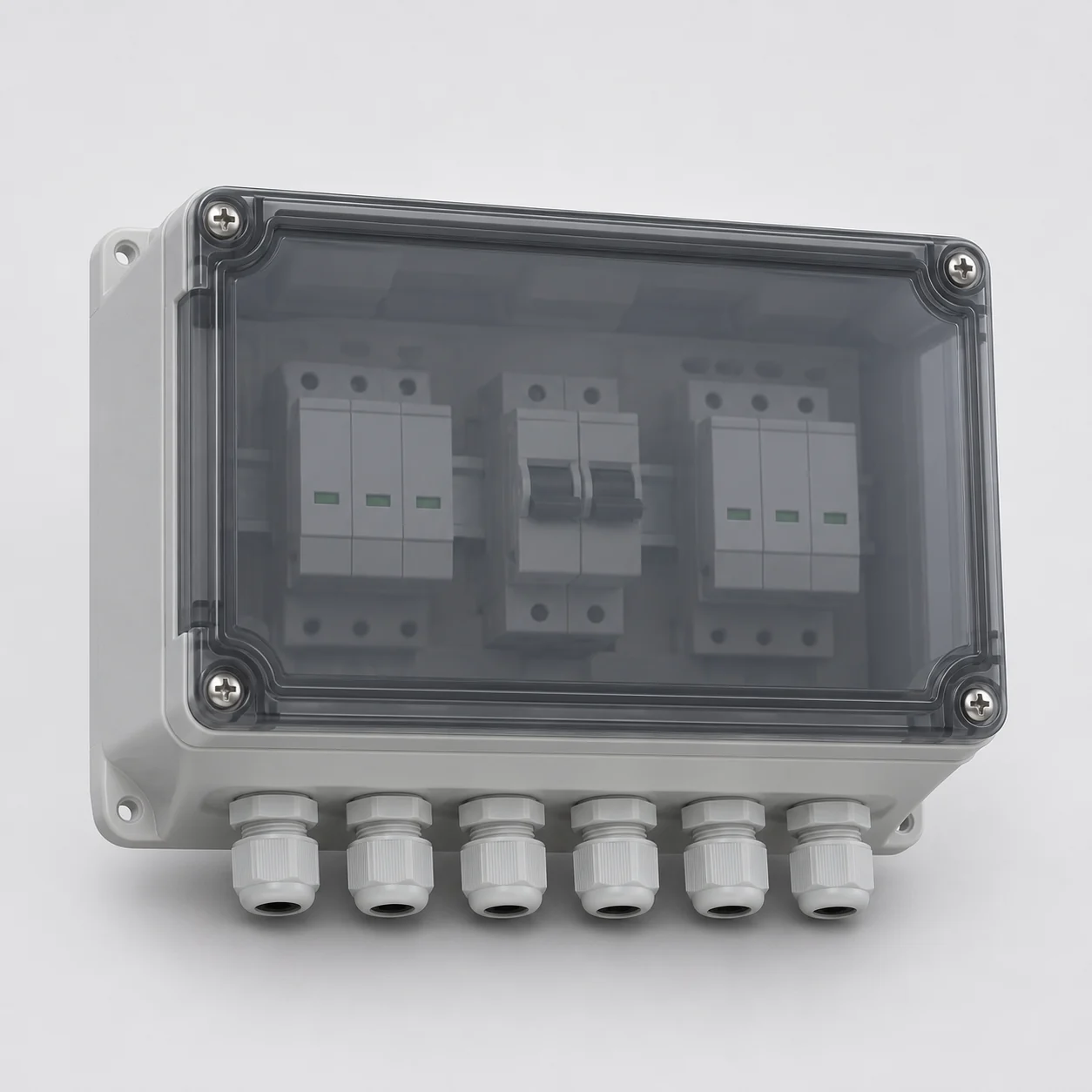
Generator connection boxes
For connections and possibly protection functions on the DC side. Ask with string number, inverter data and desired equipment.
Request a quote: Generator connection boxes
Characteristics and use: Generator connection boxes
Operation
A generator connection box (GAK) records connections of the PV strings. Depending on the circuit, it merges lines or passes on separate circuits. Versions may contain overvoltage protection, strand fuses or a load disconnector. The name alone does not say which functions are actually installed.
Selection features
Number of strings and independently controlled inverter inputs, maximum DC voltage, currents and existing protective devices determine the structure. Separate MPP inputs must not be equated with any parallel circuit when selected. Whether strand fuses are necessary depends, among other things, on possible backflows and module limit values.
Execution and system boundaries
An empty connection box is not a tested complete switching device combination. Electrical and thermal design, appropriate introductions, ambient conditions and the appropriate evidence are required for the fitted design. The image does not show a binding interior structure.
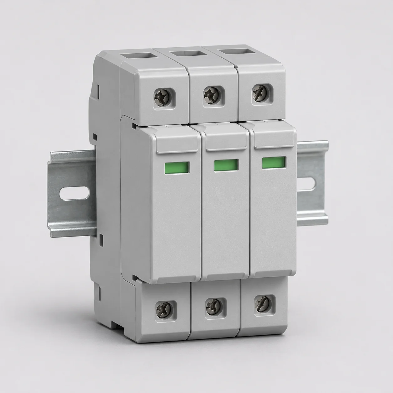
PV-DC overvoltage protection
For the planned overvoltage protection concept of your PV direct current circuits. Name system voltage, installation location and existing lightning protection.
Request a quote: PV-DC overvoltage protection
Characteristics and use: PV-DC overvoltage protection
Operation
Overvoltage protection devices limit short-term voltage peaks, for example due to lightning interference. Suitable DC conductors are used on the PV direct current side. They must be distinguished from AC conductors and fuses against overcurrent.
Protection concept
Type 2 is used to protect against induced and switching-related overvoltages. Where flash partial currents have to be taken into account, suitably sized type 1 or combined type 1+2 solutions are considered. The existing external lightning protection, separation distances, line paths and the grounding and potential balancing concept influence the selection.
Selection features and limits
Important features are the highest permitted continuous voltage Ucpv, protection level, dissipation capacity and suitability for the DC system. Protection already present in the inverter is considered; it does not replace additional conductors in each body. A dropper is not a substitute for the entire lightning protection planning.
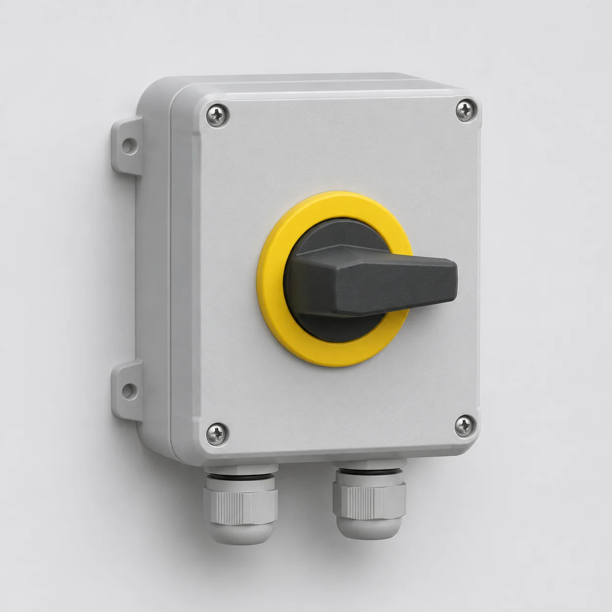
PV-DC load disconnector
For a intended switching and separation point on the PV-DC-side. Ask with electrical design data and information about the installation location.
Request a quote: PV-DC load disconnector
Characteristics and use: PV-DC load disconnector
Operation
A load disconnector designed for PV direct current can switch the intended circuit and provide a separation function. There are separate housing versions and solutions integrated into other devices. DC sets other requirements for switching than alternating current.
Selection features
Design voltage, operating current, PV category of use, pole configuration and ambient conditions shall fit the intended application. A load disconnector does not limit overvoltages nor does it automatically replace a fuse.
Limits of shutdown
Separation of the inverter does not automatically make the module field fed by daylight and the cables lying in front of it voltage-free. Remote switching or switching off at module level is a separate system function. The technical planning shall determine the necessary facilities.
On the AC side.
After the inverter, the PV system is integrated into the building installation. The requirements of the AC circuit and its protective concept apply here.
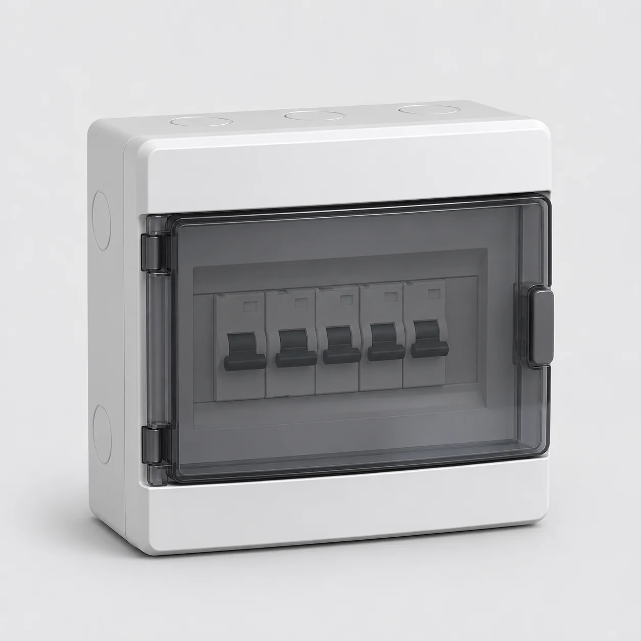
AC connector and protection distributor
For the inverter connection in the building installation. Tell us the planned structure and the existing protection devices.
Request a quote: AC connector and protection distributor
Characteristics and use: AC connector and protection distributor
Operation
An AC distributor accepts the connection and protection devices intended for the inverter output. This can include cable protection, AC overvoltage protection and – if necessary in concrete construction – fault current protection. Scope and device selection are not fixed standard assembly for each PV system.
Selection features
Grid shape, phase number, inverter data, line measurement, short circuit conditions and existing protective devices are considered together. Whether a fault current protection device is required and which type is suitable is the result of installation, relevant requirements and inverter documents; a flat-rate type assignment would be incorrect.
Coordination in the overall system
AC conductors are matched with the protection on the DC side and the building protection. Housing size, installation location, heat dissipation and later accessibility also count. A connection distributor is neither automatically a counter cabinet nor a replacement current switching.
Important terms simply explained.
DC and AC
DC means DC on the PV generator side, AC AC at the power output of the inverter. Protection and switching devices are selected for the respective circuit.
String and MPP input
A string is a series circuit of PV modules. An MPP tracker controls the working point of the associated generator part. Number and allocation of inputs influence the connection box.
SPD and type 1 / type 2
SPD stands for surge protection device. Type 1 is designed for flash current stress, type 2 for induced and switching-related overvoltages. Selection and combination are based on the protection concept.
Ucpv and level of protection
Ucpv is the highest permanently permissible PV voltage on the conductor. The protection level describes the stress stress remaining during the discharge under the specified test conditions. Both must fit the system.
Load separation and overcurrent protection
Load separation switches and separates a dedicated circuit. Backups or cable protection devices respond to overcurrent. The functions are different, even if they sit together in a housing.
IP protection class and protection class
The IP protection class describes the protection against contact, foreign objects and water in the intended structure. The protection class concerns measures against electric shock. A high IP number does not confirm the electrical design or UV resistance.
What does the selection matter?
Starting point are plant plan, inverter data, string and MPP assignment as well as the existing AC installation. Design, protective devices and housings are selected for DC or AC and for local conditions. External lightning protection, grounding and potential balancing belong in the coordination. The electrical engineering design defines the complete protective concept.
This information will help us with your offer.
Name the desired function and the existing planning level. The data of the existing plant also help with a supplement.
- Type of accessory and task desired; new installation, addition or replacement
- Inverter data, string number, MPP assignment and known electrical design data
- Existing protective equipment, installation plan and information on external lightning protection and grounding
- Location, environmental conditions, required number; photos and documents, if available
Photos and existing documents can be added directly to the contact form.
Frequently asked questions.
Does each PV system need the same generator connection box?
No, no, no. String construction, inverter inputs, electrical design and already existing protective devices differ. Also fuses, overvoltage protection and separation function are no fixed standard equipment of each box.
Is everything voltage-free after operating a DC disconnector?
No, no, no. The illuminated PV modules and the cables located in front of the separation point can continue to cause voltage. The concrete plant and protection concept results from which separation or shutdown functions are provided.
Technical basis.
View Sources
These principles explain protection tasks and component types. They are not a connection guide and no proof of a specific assembly. The current technical planning, the applicable standards and the documentation of the selected devices are decisive.
VDE: Lightning protection of photovoltaic systems
DKE: Overvoltage protection for AC and DC systems
DKE: PV overvoltage protection devices – EN 61643-31, short version
DKE: Load switch and load disconnector – DIN EN IEC 60947-3, short description
DKE: PV power supply systems – scope of the 2022 draft standard
Enquire protection and connection for your PV project.
Send us your needs and the existing documents. We will coordinate the required execution with you and prepare your offer.